Friday, February 8, 2019

Jersey 2.26 and injection changes

What changed in Jersey 2.26+ ?

    If you look at the release notes for Jersey 2.26 there is a brief note about changing the dependency injection mechanism. There is not much detail on how this is going to impact a user of some of Jersey's features - specifically injecting method parameters. Quoting from the release notes:
attempt to make Jersey core independent of any specific injection framework. As you might now, Jersey 2.x is (was!) pretty tightly dependent on HK2, which sometimes causes issues (esp. when running on other injection containers. Jersey now defines it's own injection facade, which, when implemented properly, replaces all internal Jersey injection.

Jersey source commits of interest

    For the adventurous souls, the following is a list of commits that changed the classes, interfaces and mechanisms around field and method parameters injection.

It is fascinating to trace the changes that were gradually introduced, including the name changes, simplification and rationalization.

The core changes are around AbstractValueFactoryProvider, ValueFactoryProvider and the mechanism for actually getting to the value to be injected.

So what should I do?

  1. Replace usage of org.glassfish.jersey.server.spi.internal.ValueFactoryProvider with org.glassfish.jersey.server.spi.internal.ValueParamProvider.
  2. Replace usage of org.glassfish.jersey.server.internal.inject.AbstractValueFactoryProvider with org.glassfish.jersey.server.internal.inject.AbstractValueParamProvider.
  3. If your implementation of AbstractValueFactoryProvider had a super call, note that the constructor signature has changed. The constructor parameters are now Provider mpep, Parameter.Source... compatibleSources.
The best is yet to come.
.
The return type of AbstractValueParamProvider.createValueProvider() is now
java.util.function.Function
So you need to create a FunctionalInterface that returns the object that you need.

Once these changes are made your parameter injection will work just as before. To make things more future-proof it will be best to use the new AbstractBinder and Binder that Jersey 2.26 has introduced.  This will decouple your code very firmly from HK2.

It is still a matter of concern that these classes are 'internal' Jersey classes. Thus there is lack of documentation and no clear warning on changes.

Tuesday, October 24, 2017

Communicate or die

From web services to micro-services

All the world talks about the "Cloud". Along with this came the buzzword "micro-services", Now the emphasis is on Machine Learning and Artificial Intelligence. We will leave the latter for later. I will not go into an argument about how micro-services is the new SOA, SOA done right or special case of component-based architecture. Those topics have been done to death by everyone and their dog. Don't even get me started about "Simple Object Access Protocol'. In this post I would like to think aloud about a specific communication pattern between services.

Make no mistake about it, there are no silver bullets in the world. My brother is a civil engineer. He designs and builds things that I can only marvel at. I was fortunate in being able to work through his textbooks on hydrodynamics, strength of materials, bridge design and other esoteric concepts. One point that all of those design-related works emphasized was that what you gain on the straight-aways you lose on the roundabouts. In the technical architecture world this is much more evident.

The idea behind micro-services is to have a modular service that may be looked up, is fault-tolerant and can be set up in a cluster. Services are not without side-effects. Side-effects occurring in one service may need to be communicated to another service (or a group of services). How can these services know about each other? If one service stores information about another service, then the services are no longer independent. We may have yet another service that stores information about the services. So when any service needs to communicate some information to another service, all it has to do is consult the 'locator' service. But then this 'locator' service becomes a bottle-neck and point-of-failure. Luckily there are industry-standard 'locator' services that you may weave into your product

Alright, 'where' is solved

'Locator' services help looking up services. But a service might expose multiple endpoints. Of course, these endpoints can change as and when needed. This means that either the 'locator' service needs to carry this information or else the calling service needs to carry it. In either case we then have to 'flush' the service. This also becomes a somewhat unacceptable level of inter-service knowledge. Think also about the case where state change in one service needs to be communicated to more than one service with the source service not having to know which all services need a piece of information at a given point of time.

Eventing subsystems to the rescue

Almost all programming languages have the concept of events and event listeners. They allow the source of state changes to supply events that are then handled, in their own way, by interested listeners. Listeners have the responsibility of registering with the source of events that they would like to be informed about. This model can be extended to the world of micro-services. If we set up a registration-based system for services, listener services can sign up for receiving events. The service that accepts the registration should also accept information about the listener endpoint. So now we have the 'locator' service supplying the location of the target service and 'event transmitter' service that contains the target service's endpoint information. This 'event transmitter' service can be made as simple or as complex as your service habitat demands. It can support complex filtering rules that determine whether an event needs to be supplied to a registered target service, chunking the events if the size exceeds certain limit, securely signing the events, to give some examples. It can also be an 'active' or 'passive' (or both) component. Operating in the 'active' mode, the 'event transmitter' would actively try to deliver incoming events to targets. In 'passive' mode the service would wait till a registered service asks for events.

But you never told me

What happens when the target service has gone down or is not reachable? Your active 'event transmitter' will still try to pass on the events, but they will not reach the intended recipient. If you are using a 'passive' mode and there is an expiration time set on the event, then it may happen that the target service does not ask for events before the expiration time has passed. When building component systems we always have to design for failure.
One solution for this 'failure in delivery' is to have a dedicated 'delivery error' event stream maintained by the 'event transmitter'. Any event that could not be delivered to a target is dumped into this error stream along with information about which target was unable to receive this event. The error stream may be made persistent.

And so on .....

This 'error stream' can be put to uses that are only limited by your imagination. It can be used by your 'monitoring service' to track endpoints going out of reach. It can be used by the target service to recover lost events when they come back up.
Hopefully you now have an inkling of the role of events in a world of interacting services and how the rough edges may be smoothed out. The rest is left as exercises in ingenuity.

Friday, January 22, 2016

ODI 12c SSL configuration

SSL configuration in ODI

Prior to 12c ODI was able to use OdiInvokeWebservice tool to access webservices over SSL and also invoke operations on remote ODI Agents over SSL. Late in the 11g release train - by 11.1.1.7.0 - it was also possible to setup an ODI Standalone Agent in SSL mode. But the configurations for all these were a bit confusing, to say the least.

With ODI 12c there was an effort to simplify and unify all the configuration options and also add more flexibility in the SSL configuration.

A rose by any other name

There are multiple Agent configurations, when you really come to think about it. There is Studio Local Agent, Jetty-based Standalone/Collocated Agent and also JEE Agent that runs within WLS. Each of these requires some sort of configuration to be able to call out to HTTP services over SSL or, in the case of Standalone/Collocated Agents, be able to serve requests over SSL. We will look at each of these separately.

Note that Java 'keytool' is your friend for creating/importing/exporting certificates. Read up about its functionality in the standard JDK Javadoc.

Standalone/Collocated Agents over SSL

In order for these Agents to be SSL-enabled the first requirement is that you must edit 'instance.properties' file to set 'PROTOCOL' to 'https'. Then you must provide the location of a keystore file. This location is supplied through the standard Java system property 'javax.net.ssl.keyStore'. It is defined in 'instance.cmd/sh' file. Note that the location of instance.properties file and instance.cmd/sh file are a little peculiar. You will find them under /config/fmwconfig/components/ODI/[/bin].

By default the keystore location points to the domain's demo identitystore. For initial testing you can use this, but be sure to change the location and keystore for any production use. This keystore file must contain the SSL certificate for the server. The next piece of information to provide is the keystore password. The password has to be ODI-encoded password. Use the encode.cmd/sh shell script to convert plaintext keystore password to ODI-encoded format. This value is then to be stored in 'instance.properties' as value of ODI_KEYSTORE_ENCODED_PASS. If the key itself is password-protected this password too must be ODI-encoded and stored as value of ODI_KEY_ENCODED_PASS.

An additional configuration that can be performed is to disable less secure SSL ciphers. This can be done using ODI_EXCLUDED_CIPHERS - also from instance.properties. The names of the ciphers to be excluded are to be provided as a comma-separated list. If Agent has been started at INFO level or more verbose logging and at least one cipher name is set for this property, then you can see a list of ciphers available in the JVM printed out to the log. This list can then be used for further pruning of less-secure ciphers, if necessary.

JEE Agent SSL

In this case no configuration is needed. WLS takes care of SSL transport.

Standalone/Collocated/JEE Agent as SSL client

OdiInvokeWebservice or OdiStartScen tool in ODI Package/Procedure can require SSL configuration if the remote endpoint is only accessible over SSL. For this you need to configure a truststore from where the remote server's SSL certificate may be obtained.

For Standalone/Collocated servers the truststore location and type are to be supplied via the standard 'javax.net.ssl.trustStore' and 'javax.net.ssl.trustStoreType' in 'instance.cmd/sh'. The truststore password is to be supplied as ODI-encoded string set as value of 'ODI_TRUST_STORE_ENCODED_PASS' in 'instance.properties'.

For WLS, the standard Java properties will already be available, but you will need to provide the truststore password by setting 'ODI_TRUST_STORE_ENCODED_PASS' as a system property and its value as the ODI-encoded password string. You can use the domain script or the Managed server script for adding this system property. This does create a limitation that a WLS Managed server having more than one ODI Agent can only support one truststore.

Default WLS truststore location : /server/lib/DemoTrust.jks
Default WLS truststore password : DemoTrustKeyStorePassPhrase
WLS Domain keystore : /security/DemoIdentity.jks

ODI Studio Local Agent as SSL client

Pre-12c you would have had to add the SSL Java system properties as well as the 'ODI_TRUST_STORE_ENCODED_PASS' in odi.conf file. But starting from 12c you can go to Tools -> Preferences -> Credentials to configure your truststore. These will be available as standard Java system properties for Studio Local Agent. In case this does not work you can directly add the SSL system properties and ODI-encoded truststore password in odi.conf.

Monday, February 9, 2015

Creating a JSON file

Oracle Data Integrator and JSON

    Oracle Data Integrator 12.1.3 adds the capability to read and write JSON files. Both of these work through the Complex File dataserver definition of ODI. There does exist one limitation to JSON capability in that the JSON data must have a single root. This is analogous to XML dataserver in that a recurring element cannot be used as the root element.
    In order to specify that the Complex File dataserver is meant to read and write JSON file, a new property has been added to Complex File technology viz. "translator_type" or "tt". For JSON reading and writing the value of this property must be set to "json". For other types of Complex Files do not specify this property at all.
    If the Complex File dataserver has associated with it the XSD generated by Native File Format wizard then there is no need to explicitly provide this property specifying the translator type. If you look into a generated XSD file, it will have an annotation nxsd:version=JSON. For other source formats, the wizard will generate XSD file with annotation nxsd:version=NXSD.
   One more item of interest is that the Complex File dataserver accpets all the commands and properties supported by XML driver. So you can - for intents and purposes - treat Complex File technology as XML technology.

Getting our feet wet


    Let us jump right in and see an example about reading (and writing) a JSON file. Shown below is the JSON that we are going to use as source.
JSON
{
"completed_in": 0.012,
"max_id": 130,
"max_id_str": "136536013832069120",
"next_page": "?page=2&max_id=136536013832069120&q=twitterapi&rpp=1",
"page": 1,
"query": "twitterapi",
"refresh_url": "?since_id=136536013832069120&q=twitterapi",
"results": [
{
"created_at": "Tue, 15 Nov 2011 20:08:17 +0000",
"from_user": "fakekurrik",
"from_user_id": 370,
"from_user_id_str": "370773112",
"from_user_name": "fakekurrik",
"geo": null,
"id": 136,
"id_str": "136536013832069120",
"iso_language_code": "en",
"metadata": {
"result_type": "recent"
},
"profile_image_url": "http://a1.twimg.com/profile_images/1540298033/phatkicks_normal.jpg",
"source": "<a href="http://twitter.com/">web</a>",
"text": "@twitterapi, keep on keeping it real",
"to_user": "twitterapi",
"to_user_id": 62,
"to_user_id_str": "6253282",
"to_user_name": "Twitter API"
}
],
"results_per_page": 1,
"since_id": 0,
"since_id_str": "0"
}

The corresponding XSD file shall be


As you can see it has the attribute nxsd:version="JSON". Also you can see that the XSD has a root element called "tweet". Do not be concerned. This is just an empty holder.

    We shall be using the same XSD for defining source and target Complex File dataservers, but with different value for the "s=" parameter of the dataserver.

    Let us define the source Complex File dataserver. See below the definition.


You can see that the "tt" property is set. This is to clarify the nature of the dataserver. Now create Physical Schema, Logical Schema and a Model for this dataserver. See below the Model and datastores that will get created.


Now create a target Complex File dataserver.


As can be seen the "f=" parameter is not specified. So this dataserver will not have any content. It will only have a shape. Also note the different value given to "s=" parameter. Again create Physical Schema, Logical Schema and Model for this dataserver.


Now that we have the Models created, let us create a Mapping. Create a Mapping with empty dataset. Then multi-select (Ctrl-click) all datastores from "twitter_simple" model. Darg-drop them into the default dataset. Re-arrange them to see all the datastores.

Now multi-select all datastores from "twitter_simple_targ". Darg-drop them outside of the default dataset. Re-arrange them. Create mapping from the dataset to each of the three target datastores. Choose to do auto-mapping in each case. You will end with the following.


Execute this mapping once to verify that there are no errors. No file will be created, so do not look for it. We are just populating data into the target via this Mapping.

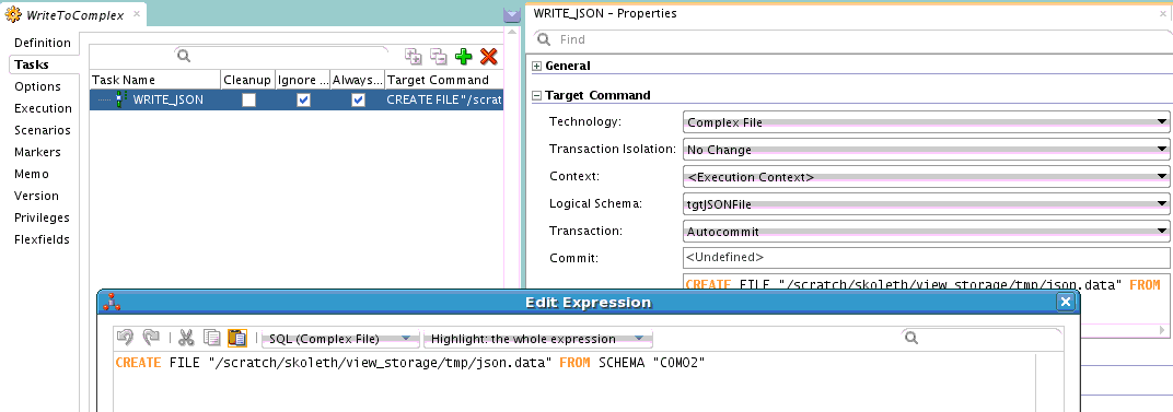
Next step is to actually write out the data into a JSON file. For this we will use a Procedure and the 'CREATE FILE' XML driver command.


The JSON file is being created from the schema of the target Complex File dataserver. Since we want this Procedure to be executed *after* the Mapping, but in the same Session so that we will get the data, we shall put the Mapping and Procedure into a Package.


Execute this Package. The contents of our initial JSON file will get written out to the new JSON file. You will notice that the psuedo-root node "tweet" is absent in the result.

This is a basic example of reading (and writing) JSON file using Oracle Data Integrator. More complex flows can be created and the source/target of data can be changed. The main take-aways should be about the pseudo-root and the fact that Complex File technology works the same way as XML technology and accepts the same properties and commands.

Note:

In the mapping shown  above, all the target tables are in the same mapping. This depends on the Parallel Target Table load feature of ODI and has all its limitations. Please verify that your target tables are indeed capable of being loaded in parallel. Otherwise you will need to create one mapping per XML hierarchy level.

Tuesday, September 23, 2014

New and noteworthy in ODI 12.1.3 XML driver

Rich metadata

One of the most important features added to the XML (and by extension Complex File) driver in Oracle Data Integrator 12.1.3 is support for user-control of generated table names, column names, column datatype, column length and column precision. This is made possible by the user being able to add custom attributes to those elements/attributes whose corresponding relational (and by extension the ODI Datastore) structure they want to control.

Why add this to XSD?
Some users might ask this question. For example, the ODI LDAP driver allows you to specify an 'alias_bundle' where LDAP DN names can be aliased to a more meaningful table name. The down side to this is that it becomes another file that you need to keep and move around according as the location of your Agent that actually performs the execution.

Details about this feature can be found in the XML driver documentation here. However here are couple of tips that will be of use.
  • XML driver creates tables for complex elements as well as elements of simple type with maxOccurs > 1. In the latter case a table is created for the element and the data in each of the element instances in the XML is stored in a column with the name '_DATA'. If user wants to control the datatype, length or precision of this column, user can go ahead and add column metadata to this element.
  • Tables cannot store data from multiple elements. Suppose you have a global element of complex type or maxOccurs > 1 in your XSD and also more than one place in your XSD where this element is used via 'ref'. In this case you cannot control the table name for this element.

Recursion support

Until 12.1.3, compat_mode=v3 mode did not support recursive XML structures. If user supplied an XSD with recursive structure, it would result in an exception that said in effect 'recursion not supported'. From 12.1.3 onwards the driver supports recursion. More information may be found in this post.

ODI XML driver and recursion

The serpent Set swallowing its tail


Most well-designed XSDs avoid recursion. But certain XSDs that are generated by frameworks or by naive Object hierarchy to XML hierarchy conversion tools make heavy use of recursion. In the v2 mode of XML driver this was handled in a spotty manner. Relational structures get created, but data may or may not be populated properly. Some element data may disappear altogether. The v3 mode driver that was introduced in ODI 11.1.1.7.0 and made the default in ODI 12.1.2 uses element xpath to uniquely identify an element. This causes a problem with recursion since each recursion occurrence is a unique xpath and will lead to creation of a new table ad infinitum. This will result in a StackOverflowError. To avoid this, 11.1.7.0 and 12.1.2 XML drivers raise error when recursion is detected.

Breaking the chains


It is obvious that avoiding recursion is not the answer. Hence in ODI 12.1.3 recursion support was added to v3 mode. Broadly speaking there are two types of recursion - self-recursion and multi-element recursion. An example for self-recursion is /CustomerOrder/Order/Order. Multi-element recursion - which is more common - can be exemplified by /CustomerOrders/Order/Return/Order.

XML driver breaks the recursion loop by first detecting the recursion and then identifying the recursion head and recursion tail. For self-recursion, recursion head == recursion tail. In the multi-element recursion above, the recursion head is /CustomerOrders/Order and the recursion tail is /CustomerOrders/Order/Return. Once this information has been identified no further exploration of this hierarchy is performed. /CustomerOrders/Order table will hold the data from all the recursion descendants of 'Order' type and /CustomerOrders/Order/Return table will hold reference to the data for all the recursion descendants of 'Order' type.

So one thing a user may expect with recursion is that even if your XML data has, say 100 levels of recursion, the XML datastores will only have one level representing this whole recursion hierarchy. The driver takes care of folding in and unfolding out the XML data as it is read in or written out. However, if user wants to perform a mapping from or to such a datastore, then they need to make sure that they pay attention to the PK-FKs on the tables so that the mappings to or from different recursion levels do not overlap.  For self-recursion, the ORDER table will have, as usual, an ORDERPK column. In addition it will also have an ORDERFK column. An Order element having an Order child will have the child element's PK reference in the ORDERFK column. In a similar manner, for the multi-element recursion example, RETURN table will have an ORDERFK column that will contain reference to Order children of Return.


Thursday, May 15, 2014

Using ODI to create a Complex File

Reading, writing and .............


It is trivial to configure a Complex File dataserver, reverse engineer it and then read data from the datastores. It is a little cumbersome, but no black magic to do the reverse of it. But there seems to be an impression that there is some arcane process involved in writing out a new Complex File. In this post we shall examine the steps needed to write out some data to a Complex File.

First of all let us configure a Complex File dataserver.


As you may see there is nothing fancy. Just to make things a little more interesting I have added the XML driver property 'ldoc=false' (load on connect = false). This gives me control over when data is actually loaded. Now I test the connection and reverse engineer. This leaves me with the model seen below.

Since I want to explicitly load data into this model I need to create an ODI Procedure. Create a new Procedure and add a Task. All that the Task does is load data from the file that is specified in the JDBC URL into the datastores.


In the above screenshot you can see the configuration of the Task. The Technology is set to 'Complex File', the Logical Schema is set to that of the source dataserver that we have set up. The command to execute is the XML driver's SYNCHRONIZE command.

Only Target Command has content. Source Command section is empty for this Task.

Now we are ready for a target. Use the same XSD as the one for the source dataserver and create a new Complex File dataserver. Be sure to choose a different value for the 's=' property in the JDBC URL of this dataserver. Also see that there is no 'f=' property. We only want the bare datastores for the target. Data in it is going to come from the source.


As before, reverse engineer to create a model and datastores. This will result in a structure equivalent to the one for the first dataserver. Note that we are doing it this way just for our convenience. Nothing stops you from using totally different XSDs for the source and target.

Now comes the part of actually populating the target with data. For this create 4 mappings. Each mapping will take care of moving data from one of the source datastores to the corresponding target datastore. Let us look at the first mapping, an in-between mapping and the last mapping.

First mapping:


As you may see, it is very simple. Just the root element from source is mapped to root element of target. I have chosen to use an Oracle dataserver as my staging area, but this is irrelevant.

The LKM and IKM are the default ones - LKM SQL to SQL (Built-in).GLOBAL and IKM SQL Incremental update - with FLOW_CONTROL and TRUNCATE turned off.

In-between mapping:


This is the mapping between CUSTOMERCHOICE datastores of source and target. Again staging area is the Oracle dataserver. KMs are as for the ones in the first mapping.

Last mapping:


The last mapping is the one with ITEMCHOICE.

Now we have moved data from source datastores into target datastores. What we need to do next is to push this data out into a complex file. In order to do this we need another ODI Procedure. This time the Procedure Task will use XML driver's CREATE FILE command.

Here is the Procedure Task. As before the Technology is set to 'Complex File' and Logical Schema is set to the target dataserver's logical schema. The command is 'CREATE FILE FROM SCHEMA "COM02" where 'COM02' is the value of the 's=' property set on the JDBC URL of the target dataserver.

Next step is to assemble all these Mappings and Procedures into a control flow. For this we use an ODI Package.

Execute this Package and you will see the data that you loaded into the target datastores written out into a complex file that follows the structure that is defined by the XSD associated with the target dataserver. That is it.

What if .....

One error you might encounter when trying to write out the data is 'Start of root element expected'. This error means that the XML data being written out does not conform to the XSD file that you have used for configuring the Complex File data server. There is no easy way to debug this. But here is something you can try.

Use the XSD file that has been used in the Complex File dataserver to set up an XML dataserver. Create exactly same Interfaces/Mappings and Procedure as you have used for the Complex File creation, but this time using the XML datastores as the targets. Now write out the data and examine it. If the problem is in the root element you can spot it immediately. Otherwise you can use the Native File Format command line to test the generated XML against the XSD. Follow the instructions in this blog post.