Showing posts with label Oracle Data Integrator. Show all posts

Monday, February 9, 2015

Creating a JSON file

Oracle Data Integrator and JSON

    Oracle Data Integrator 12.1.3 adds the capability to read and write JSON files. Both of these work through the Complex File dataserver definition of ODI. There does exist one limitation to JSON capability in that the JSON data must have a single root. This is analogous to XML dataserver in that a recurring element cannot be used as the root element.
    In order to specify that the Complex File dataserver is meant to read and write JSON file, a new property has been added to Complex File technology viz. "translator_type" or "tt". For JSON reading and writing the value of this property must be set to "json". For other types of Complex Files do not specify this property at all.
    If the Complex File dataserver has associated with it the XSD generated by Native File Format wizard then there is no need to explicitly provide this property specifying the translator type. If you look into a generated XSD file, it will have an annotation nxsd:version=JSON. For other source formats, the wizard will generate XSD file with annotation nxsd:version=NXSD.
   One more item of interest is that the Complex File dataserver accpets all the commands and properties supported by XML driver. So you can - for intents and purposes - treat Complex File technology as XML technology.

Getting our feet wet


    Let us jump right in and see an example about reading (and writing) a JSON file. Shown below is the JSON that we are going to use as source.
JSON
{
"completed_in": 0.012,
"max_id": 130,
"max_id_str": "136536013832069120",
"next_page": "?page=2&max_id=136536013832069120&q=twitterapi&rpp=1",
"page": 1,
"query": "twitterapi",
"refresh_url": "?since_id=136536013832069120&q=twitterapi",
"results": [
{
"created_at": "Tue, 15 Nov 2011 20:08:17 +0000",
"from_user": "fakekurrik",
"from_user_id": 370,
"from_user_id_str": "370773112",
"from_user_name": "fakekurrik",
"geo": null,
"id": 136,
"id_str": "136536013832069120",
"iso_language_code": "en",
"metadata": {
"result_type": "recent"
},
"profile_image_url": "http://a1.twimg.com/profile_images/1540298033/phatkicks_normal.jpg",
"source": "<a href="http://twitter.com/">web</a>",
"text": "@twitterapi, keep on keeping it real",
"to_user": "twitterapi",
"to_user_id": 62,
"to_user_id_str": "6253282",
"to_user_name": "Twitter API"
}
],
"results_per_page": 1,
"since_id": 0,
"since_id_str": "0"
}

The corresponding XSD file shall be


As you can see it has the attribute nxsd:version="JSON". Also you can see that the XSD has a root element called "tweet". Do not be concerned. This is just an empty holder.

    We shall be using the same XSD for defining source and target Complex File dataservers, but with different value for the "s=" parameter of the dataserver.

    Let us define the source Complex File dataserver. See below the definition.


You can see that the "tt" property is set. This is to clarify the nature of the dataserver. Now create Physical Schema, Logical Schema and a Model for this dataserver. See below the Model and datastores that will get created.


Now create a target Complex File dataserver.


As can be seen the "f=" parameter is not specified. So this dataserver will not have any content. It will only have a shape. Also note the different value given to "s=" parameter. Again create Physical Schema, Logical Schema and Model for this dataserver.


Now that we have the Models created, let us create a Mapping. Create a Mapping with empty dataset. Then multi-select (Ctrl-click) all datastores from "twitter_simple" model. Darg-drop them into the default dataset. Re-arrange them to see all the datastores.

Now multi-select all datastores from "twitter_simple_targ". Darg-drop them outside of the default dataset. Re-arrange them. Create mapping from the dataset to each of the three target datastores. Choose to do auto-mapping in each case. You will end with the following.


Execute this mapping once to verify that there are no errors. No file will be created, so do not look for it. We are just populating data into the target via this Mapping.

Next step is to actually write out the data into a JSON file. For this we will use a Procedure and the 'CREATE FILE' XML driver command.


The JSON file is being created from the schema of the target Complex File dataserver. Since we want this Procedure to be executed *after* the Mapping, but in the same Session so that we will get the data, we shall put the Mapping and Procedure into a Package.


Execute this Package. The contents of our initial JSON file will get written out to the new JSON file. You will notice that the psuedo-root node "tweet" is absent in the result.

This is a basic example of reading (and writing) JSON file using Oracle Data Integrator. More complex flows can be created and the source/target of data can be changed. The main take-aways should be about the pseudo-root and the fact that Complex File technology works the same way as XML technology and accepts the same properties and commands.

Note:

In the mapping shown  above, all the target tables are in the same mapping. This depends on the Parallel Target Table load feature of ODI and has all its limitations. Please verify that your target tables are indeed capable of being loaded in parallel. Otherwise you will need to create one mapping per XML hierarchy level.

Tuesday, September 23, 2014

New and noteworthy in ODI 12.1.3 XML driver

Rich metadata

One of the most important features added to the XML (and by extension Complex File) driver in Oracle Data Integrator 12.1.3 is support for user-control of generated table names, column names, column datatype, column length and column precision. This is made possible by the user being able to add custom attributes to those elements/attributes whose corresponding relational (and by extension the ODI Datastore) structure they want to control.

Why add this to XSD?
Some users might ask this question. For example, the ODI LDAP driver allows you to specify an 'alias_bundle' where LDAP DN names can be aliased to a more meaningful table name. The down side to this is that it becomes another file that you need to keep and move around according as the location of your Agent that actually performs the execution.

Details about this feature can be found in the XML driver documentation here. However here are couple of tips that will be of use.
  • XML driver creates tables for complex elements as well as elements of simple type with maxOccurs > 1. In the latter case a table is created for the element and the data in each of the element instances in the XML is stored in a column with the name '_DATA'. If user wants to control the datatype, length or precision of this column, user can go ahead and add column metadata to this element.
  • Tables cannot store data from multiple elements. Suppose you have a global element of complex type or maxOccurs > 1 in your XSD and also more than one place in your XSD where this element is used via 'ref'. In this case you cannot control the table name for this element.

Recursion support

Until 12.1.3, compat_mode=v3 mode did not support recursive XML structures. If user supplied an XSD with recursive structure, it would result in an exception that said in effect 'recursion not supported'. From 12.1.3 onwards the driver supports recursion. More information may be found in this post.

ODI XML driver and recursion

The serpent Set swallowing its tail


Most well-designed XSDs avoid recursion. But certain XSDs that are generated by frameworks or by naive Object hierarchy to XML hierarchy conversion tools make heavy use of recursion. In the v2 mode of XML driver this was handled in a spotty manner. Relational structures get created, but data may or may not be populated properly. Some element data may disappear altogether. The v3 mode driver that was introduced in ODI 11.1.1.7.0 and made the default in ODI 12.1.2 uses element xpath to uniquely identify an element. This causes a problem with recursion since each recursion occurrence is a unique xpath and will lead to creation of a new table ad infinitum. This will result in a StackOverflowError. To avoid this, 11.1.7.0 and 12.1.2 XML drivers raise error when recursion is detected.

Breaking the chains


It is obvious that avoiding recursion is not the answer. Hence in ODI 12.1.3 recursion support was added to v3 mode. Broadly speaking there are two types of recursion - self-recursion and multi-element recursion. An example for self-recursion is /CustomerOrder/Order/Order. Multi-element recursion - which is more common - can be exemplified by /CustomerOrders/Order/Return/Order.

XML driver breaks the recursion loop by first detecting the recursion and then identifying the recursion head and recursion tail. For self-recursion, recursion head == recursion tail. In the multi-element recursion above, the recursion head is /CustomerOrders/Order and the recursion tail is /CustomerOrders/Order/Return. Once this information has been identified no further exploration of this hierarchy is performed. /CustomerOrders/Order table will hold the data from all the recursion descendants of 'Order' type and /CustomerOrders/Order/Return table will hold reference to the data for all the recursion descendants of 'Order' type.

So one thing a user may expect with recursion is that even if your XML data has, say 100 levels of recursion, the XML datastores will only have one level representing this whole recursion hierarchy. The driver takes care of folding in and unfolding out the XML data as it is read in or written out. However, if user wants to perform a mapping from or to such a datastore, then they need to make sure that they pay attention to the PK-FKs on the tables so that the mappings to or from different recursion levels do not overlap.  For self-recursion, the ORDER table will have, as usual, an ORDERPK column. In addition it will also have an ORDERFK column. An Order element having an Order child will have the child element's PK reference in the ORDERFK column. In a similar manner, for the multi-element recursion example, RETURN table will have an ORDERFK column that will contain reference to Order children of Return.


Thursday, May 15, 2014

Using ODI to create a Complex File

Reading, writing and .............


It is trivial to configure a Complex File dataserver, reverse engineer it and then read data from the datastores. It is a little cumbersome, but no black magic to do the reverse of it. But there seems to be an impression that there is some arcane process involved in writing out a new Complex File. In this post we shall examine the steps needed to write out some data to a Complex File.

First of all let us configure a Complex File dataserver.


As you may see there is nothing fancy. Just to make things a little more interesting I have added the XML driver property 'ldoc=false' (load on connect = false). This gives me control over when data is actually loaded. Now I test the connection and reverse engineer. This leaves me with the model seen below.

Since I want to explicitly load data into this model I need to create an ODI Procedure. Create a new Procedure and add a Task. All that the Task does is load data from the file that is specified in the JDBC URL into the datastores.


In the above screenshot you can see the configuration of the Task. The Technology is set to 'Complex File', the Logical Schema is set to that of the source dataserver that we have set up. The command to execute is the XML driver's SYNCHRONIZE command.

Only Target Command has content. Source Command section is empty for this Task.

Now we are ready for a target. Use the same XSD as the one for the source dataserver and create a new Complex File dataserver. Be sure to choose a different value for the 's=' property in the JDBC URL of this dataserver. Also see that there is no 'f=' property. We only want the bare datastores for the target. Data in it is going to come from the source.


As before, reverse engineer to create a model and datastores. This will result in a structure equivalent to the one for the first dataserver. Note that we are doing it this way just for our convenience. Nothing stops you from using totally different XSDs for the source and target.

Now comes the part of actually populating the target with data. For this create 4 mappings. Each mapping will take care of moving data from one of the source datastores to the corresponding target datastore. Let us look at the first mapping, an in-between mapping and the last mapping.

First mapping:


As you may see, it is very simple. Just the root element from source is mapped to root element of target. I have chosen to use an Oracle dataserver as my staging area, but this is irrelevant.

The LKM and IKM are the default ones - LKM SQL to SQL (Built-in).GLOBAL and IKM SQL Incremental update - with FLOW_CONTROL and TRUNCATE turned off.

In-between mapping:


This is the mapping between CUSTOMERCHOICE datastores of source and target. Again staging area is the Oracle dataserver. KMs are as for the ones in the first mapping.

Last mapping:


The last mapping is the one with ITEMCHOICE.

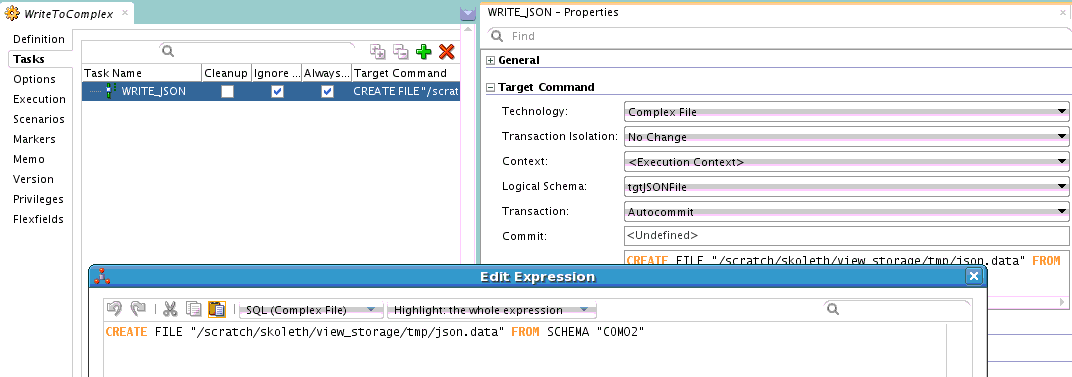
Now we have moved data from source datastores into target datastores. What we need to do next is to push this data out into a complex file. In order to do this we need another ODI Procedure. This time the Procedure Task will use XML driver's CREATE FILE command.

Here is the Procedure Task. As before the Technology is set to 'Complex File' and Logical Schema is set to the target dataserver's logical schema. The command is 'CREATE FILE FROM SCHEMA "COM02" where 'COM02' is the value of the 's=' property set on the JDBC URL of the target dataserver.

Next step is to assemble all these Mappings and Procedures into a control flow. For this we use an ODI Package.

Execute this Package and you will see the data that you loaded into the target datastores written out into a complex file that follows the structure that is defined by the XSD associated with the target dataserver. That is it.

What if .....

One error you might encounter when trying to write out the data is 'Start of root element expected'. This error means that the XML data being written out does not conform to the XSD file that you have used for configuring the Complex File data server. There is no easy way to debug this. But here is something you can try.

Use the XSD file that has been used in the Complex File dataserver to set up an XML dataserver. Create exactly same Interfaces/Mappings and Procedure as you have used for the Complex File creation, but this time using the XML datastores as the targets. Now write out the data and examine it. If the problem is in the root element you can spot it immediately. Otherwise you can use the Native File Format command line to test the generated XML against the XSD. Follow the instructions in this blog post.

Tuesday, December 17, 2013

ODI 12c debugger : row-by-row debugging

ODI is a set-based data processing tool. It does not automatically switch to a row-by-row mode for debugging. But what you *can* do is to use the IKM SQL Incremental Update. This will cause the engine to do row-by-row processing and voila! you can do row-by-row debugging.

Thursday, October 17, 2013

ODI 12c debugger

Debugging ODI is hard

Why is it so hard? Well, the following are a few reasons. ODI has tools such as OdiStartScen that will let an ODI Session launch another ODI Session on a wholly different agent. ODI interfaces (mappings in 12c) can use DB-native utilities for pumping data. This means that ODI does not have a view into the data being transferred. In ODI 12c we have introduced multi-threading in ODI Tasks. This means that like ODI Loadplans, ODI Tasks can be run in serial or parallel mode.

What have we done then?

While designing and implementing the debugger was a blast, it was disheartening to succumb to some limitations. However there are not that many of them. Just to bring it up in front, ODI debugger will let you suspend the execution flow before/after an ODI Step or before/after an ODI Task. Breakpoints can be set on design-time artifacts like Package or Procedure or on runtime artifact - ODI Blueprint.

Know your Sessions

The problem of distributed debugging is solved for the client by ODI detecting a new Session launch that is associated with a parent Session and making the client aware of the same. A caveat here is that the client must be actively debugging the parent Session. Otherwise there is no place for us to send the notification. So the good thing is that the client gets a transparent debugging experience. Don't worry, client has the option to not connect to the child Session. There are options so that even upfront you can say that the child Session is not candidate for debugging. In this case child Session is allowed run on and client cannot debug it.

See my data before or after

Data debugging is  only allowed at the beginning and ending of an ODI Task. The fact that was mentioned earlier viz. ODI may use native utilities to pump data in either direction prevents ODI from providing a transfer-by-transfer data debugging facility. However, for most usecases, the current data debugging facility will be more than sufficient, since at the end of the ODI Task we will be letting the client see uncommitted data. Note that this is a view-only tool. No modification of data is allowed. You may think of this as a limitation, but there is a way around it. ODI Debugger allows JIT modification of code. For example, if you suspend execution before an ODI Task and then modify the code of the Task, you can push that code to the repository. So when ODI gets to the point of actually executing that Task it is your modified code that will get executed. How can this help you? Well, sprinkle some dummy ODI Tasks in your ODI flow. Then when and if you see problems with your data and the next Task is a dummy Task, pause at the beginning of the Task and insert code to modify your data.

ODI threads not Java threads

ODI debugger also transparently takes care of multi-threaded tasks for the client. It provides you with a view of the threads of execution that are tied to the current ODI Session. You can see the execution stack of each of these threads and also open the Session viewer to see the precise point at which the execution has been paused. Right now, if there are multiple threads of execution in a Session and more than one of threads has been paused it is a bit difficult to make out from the Session editor's Blueprint tab as to which suspend point belongs to which thread, but it is a minor point.

See your variables' state

You will also be glad to see a variables view. Historically ODI variables have had a lot of bugs associated with it - be it actual bugs or user perception problem. The debugger can help here to a large extent in that it lets you see the ODI Variables and updates the displayed values as and when they change. Not only that the debugger will even let you dynamically modify the value of the Variable. That should be a pretty powerful tool.

So there you have it - a feature-rich debugger for ODI that should help customers and DW developers immensely.

Wednesday, October 9, 2013

ODI JMS (XML) data server peculiarities

ODI JMS data servers

ODI has JMS Queue, JMS Topic, JMS XML Queue and JMS XML Topic drivers. The Queue/Topic drivers are slightly different from XML Queue/Topic drivers. Of course the obvious difference is that the former is for Delimited/Fixed width message types and the latter is for XML message types. In addition to this there is one more subtle difference.

Go on and create a new JMS Queue data server. Give it some name and then switch to the JNDI tab. You will see drop-down for authentication type, text fields for user name and password, drop-down for JNDI protocol, text fields for JNDI Driver (the fully qualified name of the InitialContextFactory class for your JNDI server), JNDI URL and JNDI Resource.

Gotcha 101

 Many people mistakenly think that JNDI Resource is where you put the JNDI name of your Queue/Topic. This is wrong. This field is for entering the JNDI name of your JMS connection factory. It can be a custom connection factory created on the JMS server by you or an in-built one for the JMS server. If you are using Weblogic you will have the following connection factories available without any configuration : javax.jms.QueueConnectionFactory, javax.jms.TopicConnectionFactory, weblogic.jms.ConnectionFactor and weblogic.jms.XAConnectionFactory. This concludes all the configuration you can do the data server.

Gotcha 102

Did you notice anything funny? Even on the Physical or Logical schema you have no place to provide the name of JMS Queue/Topic. For this you actually have to jump through another hoop. It will be explained below. But first think about the impact of this limited configuration. You have provided JNDI URL to your JNDI server, credentials, authentication mechanism and connection factory, but no Queue/Topic information. This means that when you press that nice helpful 'Test connection' button all it is testing is creation of the InitialContext object. It does not test actual connectivity to the Queue/Topic.

Now let us say you want to connect to your Queue. Create a Model baased on the Logical Schema of your JMS Queue data server. Again, you cannot reverse engineer a JMS Queue/Topic. So you have two options :
  1. create a Datastore under this model and define the column structure by hand or
  2. make a copy of a Delimited/Fixed width File Datastore
 After the Datastore has been created there is one more thing to do : there is a text field on the Definition tab of the Datastore named 'Resource name'. For a File Datastore this would point to the actual file. This is where you enter the JNDI name of your JMS Queue/Topic.

Phew! That was a tortuous setup.

What about JMS XML Queue/Topic? Now that has some differences. For example the JNDI URL takes a key-value pair where the key is JMS_DESTINATION and the value is the JNDI name of your Queue/Topic. So all the JMS configuration is in one place. Also, a JMS XML Model can be reverse engineered.
You may now be saying to yourself 'All right!!!!!! Let me make all my JMS Queue/Topics XML-based messages'. Hold your horses, because there is a down side : you cannot right-click a JMS XML Queue/Topic Datastore and do 'Data' or 'View data'. It is not supported.

So there you are. A little the worse for wear owing to this trip over ODI JMS. Wait for the next few blog posts that will reveal to you some more hidden pitfalls and capabilities.

Sunday, July 14, 2013

ODI JMS JDBC driver gotcha


One fine morning ......

In the fullness of your enthusiasm you have built a data movement solution that takes trigger data from a JMS Queue, does some work and then writes out some information about what was actually done into another JMS Queue. But then, when the ODI Scenario is executed to your greatest horror nothing gets written out to the JMS Queue, although all tasks shine bright green in the ODI Operator.

Do you have commitment?

If this happens to you, here is one thing you can check. In ODI, tasks make use of JDBC connections. JDBC connections can be autocommit connections or be part of a transaction. JMS transactional connections have a weird behaviour. Nothing is actually written out to the JMS target until the transaction has been committed. This is a property of javax.jms.Session. For autocommit connection however, as soon as the ODI task ends, the data will be written out to JMS. In either case the one thing you can check is : after the task that writes out data to JMS do you have any task that executes using the same JMS connection, but has SQL code that consists only of SQL comment?

Explain .. explain


Assume that JMS connection is in autocommit mode. Writing out data to JMS immediately puts it in the Queue. Now you are asking JMS driver to execute some SQL that only has some comment content (no matter how this came about) using the same autocommit connection. When JMS driver tries to interpret this SQL it is unable to categorize it and as a result considers it to be a READ operation. As a result it just reads the data from the Queue. As you know a JMS read is a destructive read in that the message gets removed from the Queue. So hey presto! all your data is gone.

Now if the above sequence happens using a transactional connection during the course of the same transaction, you will not see this problem. The reason is the one mentioned above : until the transaction has been committed nothing is actually written to the Queue. Therefore the READ task is a no-op.

Coming and going

You will face the same problem if data is written using a transactional JMS connection, the transaction is committed and then you have an autocommit JMS connection that executes code that only has SQL comment.

Tuesday, April 2, 2013

What is new for ODI XML JDBC driver in Oracle Fusion Middleware 11g R1 (11.1.1.7.0)

ODI XML driver issues

ODI XML driver had several issues such as
  1. would not support elements with same name but different types. For example a local element with same namespace URI and local name as a global variable would not be handled.
  2. does not support list/union simpleTypes, any, anyType, mixed type and so on.
In ODI 11.1.1.7.0 a new compatibility mode parameter has been added. This is an XML driver property called 'compat_mode'. Its default value is 'v2'. But if you specify the value 'v3' for this parameter, you can avoid issue (1). As you might imagine, if you use 'v3' for the value of this parameter, you will run across some changes in the behaviour of the driver.

Differences between 'v2' and 'v3' modes

  1. Handling of elements with same local name and resolved type. In current XML driver, data from such elements end up stored in the same table, but the rows have different FK references. With default mode, we will use different tables to store the elements. This has implication for elements that are 'ref's of a global element. Each of the reference (and descendants) gets its own table.
  2. Determining the root element. The XML JDBC driver allows users to specify the local name of the root element, and not a qualified name. One plain assumption here is that the root element has a unique local name. In 'v2' mode, if a root element name is not specified then the first element encountered by the parser is set as root element. This is the first element from the XSD hierarchy where the XSD does not have an 'include' or 'import'. In 'v3' mode this is indeterminate. The XSD should either have only one global element or user must specify the name of the element to be used as root. Failing this, one of the global elements from one of the target namespaces is used as root.
  3. As a corollary to (2), only a global element is allowed to be used as root element. Old parser would allow use of even local elements. This is carry-over from DTD times where all elements are global elements. If user specifies a local element name (which also is not the same a global element name) then an exception is raised. Note that for the old parser, if the user had provided an XSD, then the restriction applies that root element must be a global element.
  4. When using a DTD/specifying XML driver URL parameter to generate DTD, user must provide root element name. The new XML driver converts the DTD to XSD in-memory and uses this XSD to construct the data model. This conversion requires that a root element be specified. However, DTDs that are for XML structures that need to use namespaces must continue to use 'v2' mode.

Note that since JMS XML Queue/Topic drivers and Complex File driver uses XML driver internally, these drivers will also accept 'compat_mode' parameter. 11g JMS XML driver though, will not accept this parameter. It only supports a subset of XML driver parameters. Starting from 12c this is not the case

Thursday, March 7, 2013

Use BPEL callback to asynchronously get result from ODI


Tutorial – How to use ODI callback web services in conjunction with Oracle Asynchronous BPEL

ODI 11.1.1.5.0 introduced the callback web service paradigm to ODI inbound web services. The concept is similar to the asynchronous pattern in JAX-WS. One difference here is that there is an explicit port type for receiving the callback, once the original web service invocation has completed processing. Also no connections are kept open or alive once the original invocation has been done. Let us go through the whole process of creating a SOA Application and SOA Project that calls out to ODI web service to invoke an ODI Scenario and then receive a response once the Scenario run is complete.

Prerequisites:
  • There must already be set up a Weblogic domain with SOA managed server
  • You will also need either a Standalone ODI Agent or an ODI managed server under a Weblogic domain.
  • You will need an installation of JDeveloper with SOA extension.
  • The SOA managed server must be set up as a deployment target in JDeveloper
  • Oracle Enterprise Manager must be set up on the Weblogic Admin server for the SOA managed server.

Let us start off with creating an application. I am choosing a SOA Application. You can also choose a Generic Application and configure the Project with requisite technologies.


Choose OK to go to the next page of the wizard. Here you will configure the application name, the directory in which the application files will be stored, as well as the package prefix for the application files. Choose some descriptive names.


Choose Next to continue. Here you can choose the technologies. SOA will already be selected. Add Web Services, XML.


Choose Next. Accept the defaults here unless you really want to configure specific values for the project.


Choose Next.


Here I have chosen to have an empty composite. It is easier this way for maximum flexibility. Once you click Finish, the application is created and the composite is opened.

Open the Component Palette, scroll down click and drag Web Services onto the 'External References' swimlane. A dialog will open up.

The dialog is quite self-explanatory. It is here that we need to set up reference to ODI's inbound web services. For this you need to know the URL to your ODI inbound web service. If this is your default agent deployment using the static Weblogic deployment template provided along with ODI install, the URL will be http(s)://:/oraclediagent/OdiInvoke?WSDL where and are the ones for your ODI managed server.

If you are using ODI Standalone agent, this will be of same format.

If you have created the ODI agent using a dynamic template that you created or you have customized the web application's name, you will have to find out the exact string in place of 'oraclediagent'. You can use Weblogic administration console or Oracle Enterprise Manager to help you find the exact WSDL URL.


In my case ODI is deployed using the static template with default web application name. So pointing to http://localhost:8001/oraclediagent/OdiInvoke?WSDL


See the result above. The Port Type has been set to 'requestPortType' and Callback Port Type has been set to 'requestPortTypeCallback'. This is in keeping with Oracle Asynchronous Web Service pattern. Additionally I have chosen to copy the WSDL and associated artifacts to the project so that the schema types defined in the WSDL will be readily available. Since we are targeting a static WSDL, this choice is fine.

Once you click OK a new page will be shown asking to 'Localize Files' This is to let you store the WSDL file local to the project. Choose OK here also.

See the result below. ODI web service shows up in the External References swimlane. It is time to add a BPEL process now.


From the Component Palette drag-drop BPEL Process (or you can right-click in the center swimlane and choose Insert → BPEL Process). The following dialog opens up.


Note the default choices for BPEL 1.1 and asynchronous BPEL process. Do not change the asynchronous choice to synchronous. You are going to invoke an asynchronous web service. The calls can only be from asynchronous → asynchronous.

You can change the name for the BPEL process. Make sure that 'Expose as a SOAP service' is checked so that you can easily test this BPEL.

Also since this is a simple BPEL process, the input type is being set to ODI web services input type for the operation to start a Scenario and the output to the operation's output type.

Click on the search icon to the right of the 'Input' field and navigate to OdiStartScenWithCallbackRequest type. See the image below.


In the same way navigate to OdiStartScenResponse for the output type. Note that the input type has an additional “..WithCallback...” component in the name. This is not an error.

See the final result below.


This is how the composite will look now.


Now we need to connect the BPEL with the configured ODICallbackSvc external reference to ODI inbound web service. For this bring the mouse over the 'InvokeODIWithCallback' BPEL representation in the center swimlane. Two circles with arrows inside them will show up on the lower left and lower right corners of the box. Drag from here to the green double empty arrows on ODICallbackSvc in the External References swimlane.

See the result in the following image.


So far we have been operating on the composite. Now it is time to work on the BPEL itself. Double-click on the 'InvokeODIWithCallback' box in the center swimlane. The BPEL editor will open up.

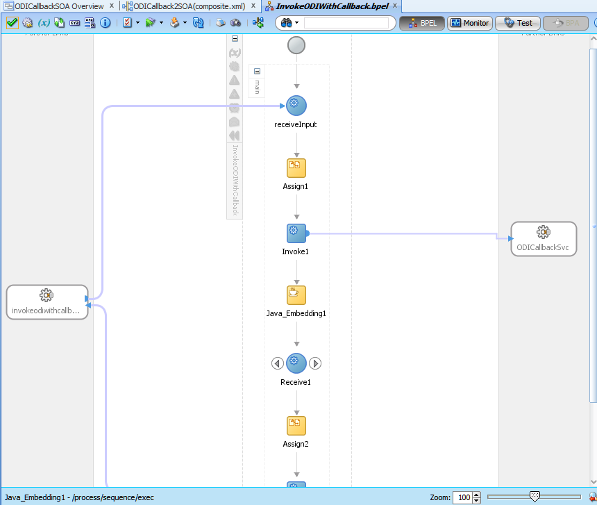
The following is what you will see. As you can see the ODI inbound web service again shows up, this time as a Partner Link. Now we need to set up BPEL process to send message to the web service and then receive asynchronous callback from the web service.


Drag-drop an Assign activity and Invoke activity, in that order, immediately after the 'receiveInput' activity. The Assign activity is for us to take the input and pass it on. Invoke activity will invoke the web service with this assigned value.


Mouse-over the Invoke activity and drag-drop from one of the arrows to OdiCallbackSvc on the right. A dialog to configure the Invoke activity opens.

Here you can choose the operation to be invoked as well as the input and output variables. Choose 'InvokeStartScenWithCallback' as the operation to be invoked. You will see that only the Input is active. Output is grayed out. This is because the output is going to to come via the callback. The response to the invocation is just an 'OK' message. It is a oneway SOAP operation.


Now we need to set up the input. For this click on the '+' sign on the right of the 'Input' field. A dialog with an automatically created variable name and the variable type required by ODI inbound web service invocation will pop up.


Choose OK both to this dialog as well as the Edit Invoke dialog.

Now we need to use the Assign activity to pass on the input to the BPEL process to this variable. For this double-click the Assign activity. In the resulting dialog expand the input to BPEL on the left pane and the variable created above on the right pane and do mapping.


Choose OK.

Now let us create a Java activity.

For this expand 'Oracle Constructs' in the Component Palette and drag-drop Java Embedding activity immediately after the Invoke activity.


Double-click the Java Embedding activity and enter the following code. This will create file whose timestamp we can verify.

java.io.File tempFile = new java.io.File(System.getProperty("java.io.tmpdir") + java.io.File.separatorChar + "time.txt"));
try {
if(tempFile.exists())
tempFile.delete();
else
tempFile.createNewFile();
} catch (java.io.IOException ioe {}

Now again expand 'BPEL Constructs' in the Component Palette and drag-drop A Receive activity followed by an Assign activity right after the Java Embedding activity.

The following image shows how the BPEL process looks now.


Now drag from the arrow on the Receive activity to OdiCallbackSvc. The following dialog is shown. Note that there are only two operations to choose from. ODI inbound web service has callback only for starting a Scenario and restarting a Session. Operations involving Loadplan are always asynchronous, so they do not have callbacks. Client has to poll for the status.


Note that there is only one 'Variable' field and no Input/Output. The Receive activity only only receives data so there is no other field. As with the Invoke activity click the '+' sign to the right of the field and accept the result.


Now we need to assign this received data to the output of the BPEL process. For this double-click the Assign activity after the Receive activity, expand the variable that was created above on the left-hand pane and the outputVariable on the right-hand pane and do mapping.


Choose OK and Save All.

In the Application Navigator right-click the Project and choose to deploy it.


Choose to deploy to an Application Server. This is the SOA managed server that user must already have set up.


Choose Next.


I have chosen to overwrite existing composites with same revision ID. Choose Next.


'SOA-ODI' is the SOA managed server that I have configured. Choose Next.


Now click 'Finish'. It will build and deploy the Project to the SOA server.

Open a web browser and enter the URL for Enterprise Manager on the Weblogic Admin server. Navigate to SOA → soa-infra → ODICallback2SOA. Then from the top SOA Composite menu, choose Test Service → the SOAP service endpoint for the BPEL process.


Be sure to choose the correct endpoint. By default it gets set to OdiInvokeCallback. You do not want this.


Rather choose the BPEL SOAP end point. Enter the required values for ODI Scenario invocation. My Scenario issues a 'beep' and then 'sleeps' for 10 secs.

Click 'Test Web Service' button.


Do not be scared. There was no response because the BPEL process is itself an asynchronous process. Click the Launch Flow Trace button. You will see the following:


For clarity I have removed the sandwiched Java_Embedding1 activity information. If you go to your 'temp' directory and look at the timestamp of 'time.txt' file you will find its timestamp to be same as the ending time for the Invoke1 activity.

Congratulations! You have created a BPEL process that will start off an ODI Session, go on and do some other things while letting the ODI Session run and at the end of the Session, ODI will call the BPEL process back with the Session ID.

Thursday, February 7, 2013

One XSD, multiple XML files

    On occasions users want to define just one XSD (set of XSDs) that define a data structure, but pull data from multiple different XML files concurrently. By applying a twist to a feature of the ODI XML JDBC driver you can accomplish this.

i)   Define an XML data server. Provide the XSD, the schema identifier (this is actually *not* used as a DB schema, but as a prefix to the tables generated for this XSD) and optionally an XML file in the JDBC URL.
ii)  Create Physical and Logical schemas for this Data Server.
iii) Create a Model based on the Logical schema and reverse engineer it.
iv)  Now you have the corresponding Datastores.

    Now comes the magic.

v)  Define a variable that takes its value from the ODI Session ID.
vi) Instead of the schema identifier set in step(i), use this variable eg: jdbc:snps:xml?d=something.xsd&s=#..
vii) Now for loading an XML file create an ODI Procedure that uses the ODI XML Driver's 'LOAD FILE' command. Again you can use an ODI variable as all or part of the XML file name.

So now for each invocation of the ODI Procedure in a Session, you will get an isolated set of DB tables that will store the data from the XML file. Instead of step(vii) you can do this directly in the XML JDBC URL also.

With a little thought this technique can be extended to allow loading multiple XML documents in the same Session using just one XSD definition.

Caveats

Be aware that XML JDBC driver limits the table name length according to the maximum length allowed for the DB. For example assume your DB allows 30 characters as the table name and your XML schema identifier is "SOME_LONG_ID". Then for an element named "thisIsanElementWithALongName", the table name as created in the DB will be "SOME_LONG_ID_THISISANELEMENTWI" (although in your ODI model the Datastore name will be "THISISANELEMENTWI").

Therefore with a dynamic schema identifier you must always limit the dynamic identifier length to the size of your initial identifier in step (i). Otherwise the XML driver will complain about not being able to find the table.

Code generation confusion

Another problem is that when ODI code generation sees a special character (#) in the schema name, it will enclose this schema name prefix in double quotes for all generated SQL statements. XML driver will not recognize such names. In a case where there are no Variables involved, if the value for the s= parameter is TEST, XML driver does not actually create such a DB schema. Instead, it will rewrite the table names so that they all have the prefix TEST_It will rewrite all SQL queries that it gets, too. Eg: select * from TEST.TABLE1; changes to select * from TEST_TABLE1. Now take the case of an ODI Variable added as a suffix to the s= value - called VAR1 that then gets resolved to '203' during runtime. The value as XML driver sees it will be "TEST203", including the quotes. When this is used for a SQL statement it becomes select * from "TEST203".TABLE1. XML driver will be unable to process the content within the quotes and the query will remain as it is. It will fail. Therefore you have to be careful using when dynamic XML Dataservers with ODI Interfaces/Mappings where ODI code generation comes into play.

So is that it?

Another way would be to keep same s= parameter value but set use the 'standalone=true' parameter. This has the effect of creating an isolated instance of the Dataserver where name collisions will not happen. There are two drawbacks to this approach
  1. Only the internal HSQL DB can be used. That means your XML data is going to reside in-memory.  This is going to impact te JVM in which the Agent is running.
  2. For each connection instance a new instance of HSQL DB itself is created. This gives additional memory overhead. Another related problem is that instances of HSQL DB may stay around. So your XML Dataserver must define an On Disconnect command sending the SHUTDOWN command to HSQL.
So what can we do to have dynamic XML/Complex File Dataservers sharing same XSD, but needing to pull from different XML files? 

Here is what you need to do : change the place where you provide the prefix for the s= parameter. A sample flow is as below:
  • create a global ODI Variable called SCH_NAME with text/alphanumeric value
  • set the refreshing query as select 'TEST_<% odiRef.getSession("SESS_NO") %>' from dual; So we are getting the Variable refresh itself to do the prefixing.
  • Now set the value of the s= parameter as #GLOBAL.SCH_NAME
  • Set the same value (#GLOBAL.SCH_NAME) as the schema and work schema in the associated Physical Schema.
Now when the SQL gets to the XML driver, it will look like  select * from TEST_4001.TABLE1; Notice the absence of quotes. This is because the code interpretation engine noticed that the entire name before variable substitution is actually referring to the name of a Variable and did not put any quotes around it.